Difference between revisions of "Mazda Protege Fan Detection Circuit Analysis"
m (1 revision) |
|
(No difference)
| |
Latest revision as of 02:16, 14 September 2013
A common problem amongst ageing 3rd generation Mazda Proteges is that the air conditioning will stop working on fan speeds 2 and 3. The failure often starts as an occasional flickering of the green "A/C" LED which can often be remedied by moving the fan speed switch back and forth a few times. Over time the light will (and the compressor) will stay off on fan speed 3 and eventually fan speed 2: no amount of playing with the switch will make it work.
Many solutions have been proposed but I don't believe anyone has examined the root cause of the problem. This page hopes to shed some light on why this happens. First we will examine the blower motor speed control circuit and then we'll take a look at the circuit that detects whether the fan is running or not.
TL;DR: If you couldn't care less about why it's not working, skip right to the how-to: Mazda Protege Fan Detection Circuit Fix
The Blower-Motor Circuit
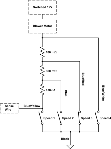
The fan speed control circuit is very basic, current is limited through the motor by a series of high-power resistors which are switched in by the speed selector switch (note that in reality only one of the speed switches could be closed at a time.
The wire labelled "Sense Wire" is the point that's used to determine if the fan is running or not. In theory when the fan is off the sense wire node will be at 12V (battery voltage) and when it's on it should be 0V (ground). Of course that doesn't happen in practice, the former is true, but the latter really isn't. In the example above there's a voltage drop across the Blue/Red wire, another voltage drop across the switch, and yet another voltage drop from the switch to ground. Add all these drops up and you probably have close to a 1V drop on an average Protege, if your A/C isn't working on speed 2/3 then that drop is over 1.1V (we'll get to that later).
So how is it that we could have such a large voltage drop over a connection which is theoretically 0 Ohms? Current!
Here are measurements taken from my car:
| Fan Speed | 1 | 2 | 3 | 4 |
|---|---|---|---|---|
| Current (Amps) | 2.75 | 6.35 | 8.8 | 11.75 |
Using this table we can see to achieve that 1V drop on fan speed 3, we only need 0.11 Ohms of resistance. That's nothing considering that all that current is passing through 3 connectors (out of the resistor block, into the switch, and back out of the switch) and Mazda thought it would be a good idea to use what appears to be 20 gauge wire for the connection between the resistor block and the switch (the blue/red wire). The voltage drop is significantly less for fan speed 4 because they used a much thicker wire for that particular speed.
The Fan Detection Circuit
The climate control unit needs to know whether the fan is running or not in order to know whether to enable A/C clutch. It uses a sense wire which is tied to the fan speed 1 switch input, and is thus active-low (when the fan is running the voltage on the sense wire is low). The problem as we'll see is that the cut-off for what constitutes a "low" voltage is much too low because of the way the circuit was designed.
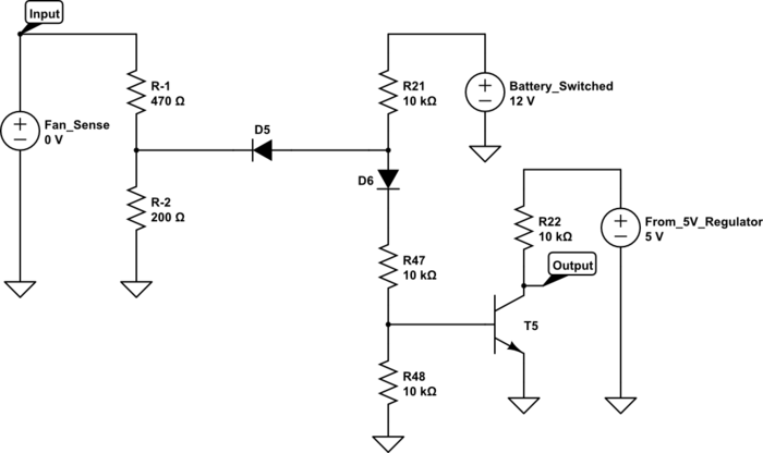
After a bit of reverse-engineering, this is what I determined to be the fan speed detection circuit:
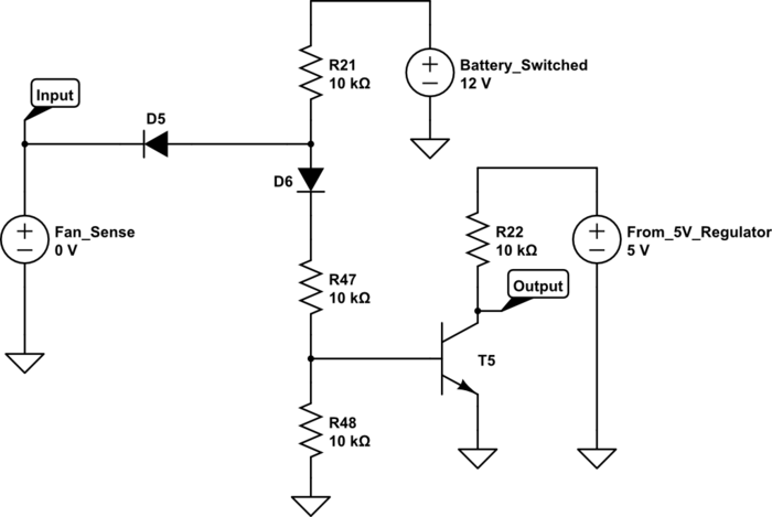
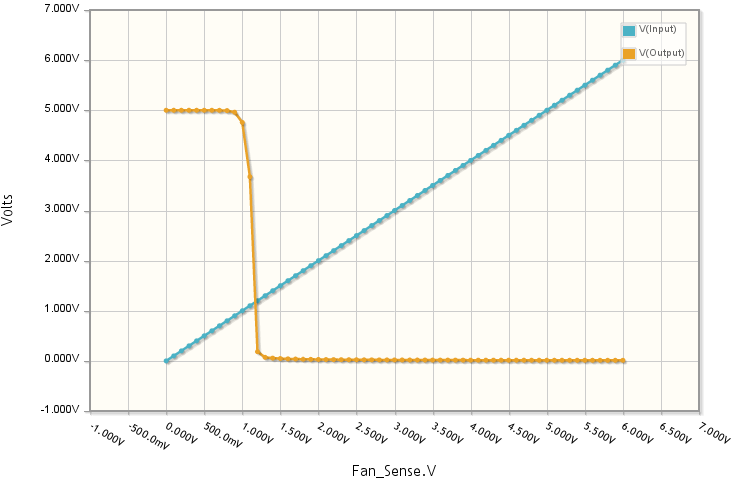
The "Input" node is connected directly to the "Sense Wire" shown in the first schematic and the "Output" node is connected through another 10K resistor (not shown) to what appears to be a custom ASIC (active-high input). The circuit is a simple inverting amplifier; I really like the built-in input protection from the diode (but that's about it). We'll see that the problem with this circuit is simply a bad choice of biasing resistors. Let's simulate it and you'll see what I mean:
It's pretty clear that anything over ~1.1V on the input will produce a logic low on the output (thus turning off the A/C compressor). For new cars coming off the line I'm sure that was more than acceptable, but after 10 years switch contacts wear-out, and connector contacts corrode. If they had some forethought they might have extended the acceptable range for the "low" voltage to ~4V (1/3 of Vcc, like everyone else does).
Fixing the Fan Detection Circuit
It's very tempting to simply replace R48 with a lower value resistor (4.7K would do the trick in case you're interested), but I wanted to provide a solution which was simple enough for anyone to do (turns out most people don't find SMD soldering very fun). The good news is we can slap a voltage divider right on the fan detection input and achieve a similar result. Here's my proposed solution:
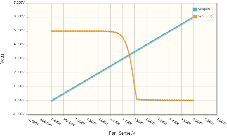
By adding that resistor divider (made up of R-1 and R-2) we get the following response from the circuit:
Now the "low" voltage cut-off is at approximately 3V which is more than adequate for our application (if there's more than a 3V drop across that wire, something's probably on fire =/). I tested this very circuit and it actually worked as expected!
I measured the voltage at the climate control's fan detection input with and without the modification and these are the results:
| Fan Speed | 1 | 2 | 3 | 4 |
|---|---|---|---|---|
| Without Modification (Volts) | 0.12 | 0.84 | 1.0 | 0.40 |
| With Modification (Volts) | 0.21 | 0.42 | 0.45 | 0.29 |
Notice that with the modification in place the input voltage is always less than half the 1.1V cut-off. Success!
For a step-by-step guide to building and installing the resistor divider, visit this page: Mazda Protege Fan Detection Circuit Fix
